
17 September, 2020
The field of perovskite/silicon tandem solar cells is a rapidly evolving research area since these tandem cells promise to achieve power conversion efficiencies (PCEs) beyond the physical limits of their individual single-junction sub cells. The facile perovskite fabrication process and its versatility in terms of bandgap engineering (the perovskite bandgap can be easily ‘tuned’ by manipulating its composition) mean that an optimal tandem configuration can be achieved in an economically feasible way compared to other approaches that use expensive III/V materials. Indeed, as well as several research groups, already a number of companies have focused on the development of perovskite/silicon tandems. However, the actual outdoor performance of such solar cells was yet to be studied and understood. Critically, outdoors test are a crucial step to understand the real performance of the solar cells before the market entrance.
To understand the real-world performance of monolithic perovskite/silicon tandems, we fabricated >25% efficient (certified at Fraunhofer ISE CalLab) devices with scalable methods, which is one of the main research focus of the KAUST Photovoltaic Laboratory. The architecture of the fabricated devices is shown in Figure 1. Later, we laminated these devices between the glass and a polymer-based backsheet, using polyolefin encapsulants - a typical mass manufacturing process for commercial silicon modules (see Figure 2)- and installed these encapsulated tandems in the solar panel test field located in KAUST, a research university on the Red Sea coast of Saudi Arabia. The test location is highly relevant since “hot and sunny climates”, typical for the Arabian peninsula, are an ideal location for the deployment of such high-performance solar cells.
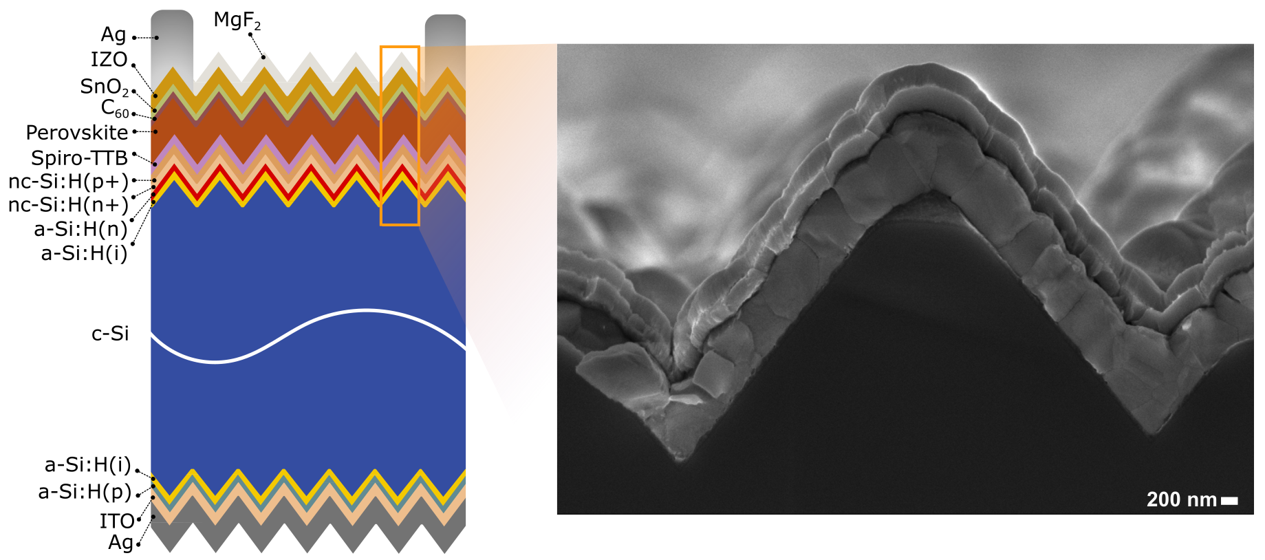
Figure 1. Device schematics and cross-section scanning electron microscopy image of the tandem solar cells used in this study.
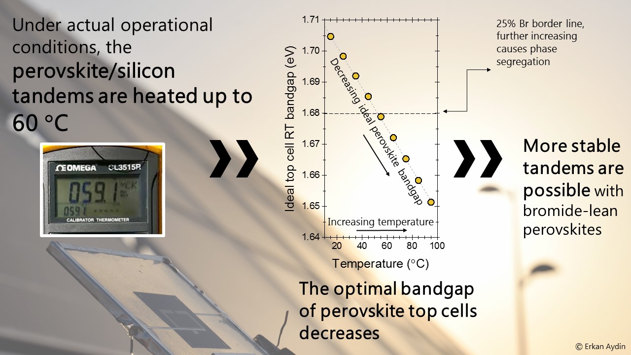
The primary motivation of the outdoor test, aside from typical stability testing (i.e., to see how the cells performed over time), was to investigate how the cells performed at actual outdoor temperatures, which are often higher than those in controlled lab environments. Solar cells, especially in hot and sunny climates, routinely reach temperatures exceeding 50 °C, even in November, which is wintertime in Saudi Arabia. This temperature change has significant consequences on the device design since the highest performance can be achieved at the current-matching condition of each sub cell in monolithic tandems, which requires a careful bandgap (Eg) optimization. However, the temperature dependence of the optical bandgaps of silicon and perovskite follow opposing trends: the silicon Eg narrows, but the perovskite Eg broadens with temperature. Therefore, we argued that to achieve the maximum performance under actual operations, the optimal Eg values, which is previously determined for standard test conditions (STC, i.e., AM1.5G spectrum, 1000 W/m2, 25 °C), needed to be corrected for the field operation conditions.
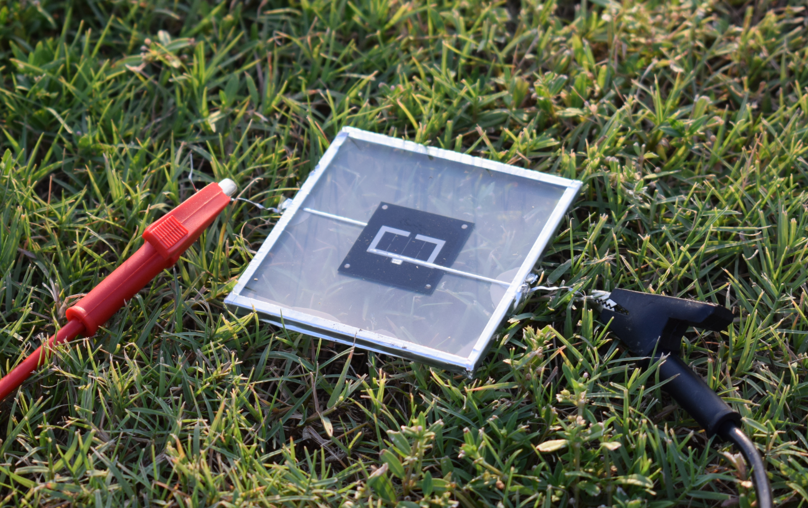
Figure 2. The photograph of the encapsulated tandem solar cells.
Later, we performed temperature-dependent radiative-efficiency modeling (Figure 3) and found that the ideal bandgap of the perovskite is less than 1.68 eV for optimal field performance at operational temperatures over 55 °C, which is lower than previously defined 1.73 eV. Significantly, this finding implies that conventional perovskites with moderate Br:I ratios can be used for tandems. This is particularly important since one of the main challenges nowadays is achieving phase-stable wide-bandgap perovskites that do not suffer from halide segregation which tends to occur for wider bandgap material. Overall, the findings in this study provide a straight-forward perovskite-design framework for the development of stable and high-efficiency perovskite/silicon tandems for commercial deployment.
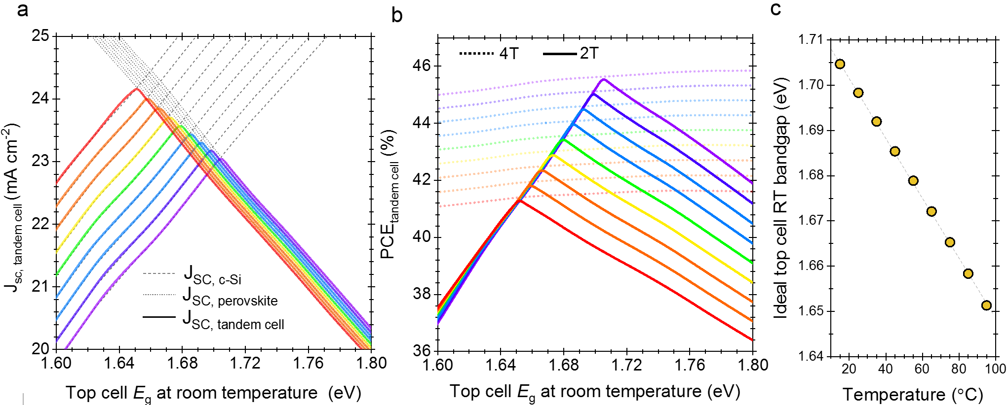
Figure 3. a, The variation of the total 2T tandem cell current as a function of the top cell perovskite Eg and cell temperature. The dotted lines show the current contribution from the perovskite subcell, while the dashed lines show the contribution from the c-Si subcell. The maximum efficiency occurs when the two values are equal. b, Corresponding PCE values for both 2T (solid lines) and 4T (dotted lines) configurations as a function of top cell Eg and temperature. c, The calculated ideal room temperature Eg of the top cell perovskite absorber at different operating temperatures. The dotted lines are guides to the eye.

Figure 4. Dr. Erkan Aydin is loading the perovskite/silicon tandem solar cells to the atomic layer deposition tool at KPV-Lab.
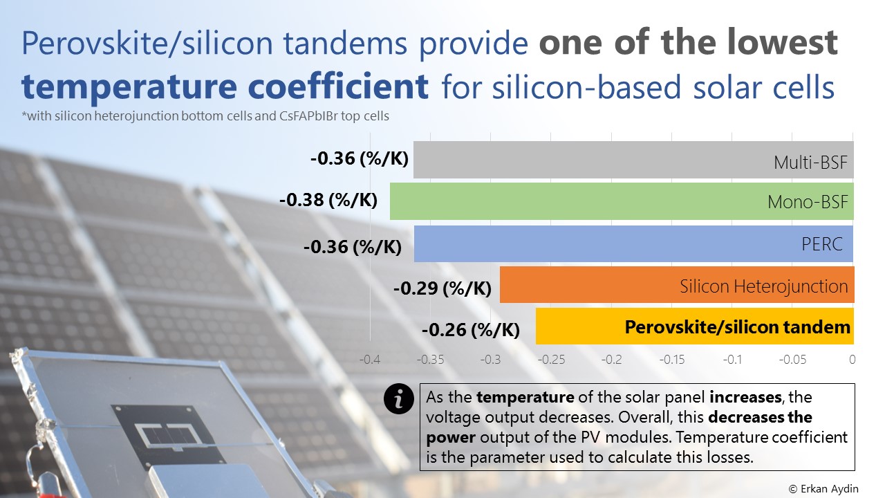
To read more about how to fabricate tandems with a record-high short circuit current, the effect of current mismatch and weather conditions on the device performance, and details of the temperature coefficient of the tandem devices, visit our recent study published in Nature Energy.
Infographics

Publication in the press